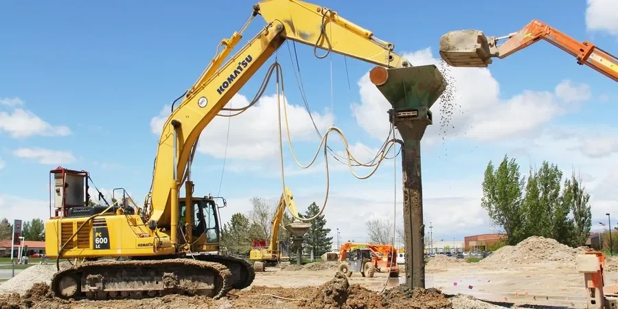
A few years back, during the site investigation for a medium-rise residential project near Lake Ginninderra, the boreholes showed over eight metres of loose, saturated sands sitting directly above weathered siltstone of the Canberra Formation. The structural loads weren’t extreme, but the differential settlement risk was unacceptable without ground improvement. Vibrocompaction design became the logical path — not as a generic solution, but as a tailored grid that needed to account for the lateral variability we see across the northern suburbs. When you’re working in a city built on an ancient sedimentary basin reshaped by Quaternary deposition, the density of granular layers can shift dramatically within a single block. Our role was to define the probe spacing, vibration energy, and depth targets so the post-treatment relative density would exceed seventy percent, which the geotechnical model demanded. This kind of site-specific design is what separates a successful stone column installation from a poorly densified fill that will settle unevenly within the first wet season.
Effective vibrocompaction design in Canberra isn’t just about reaching a target SPT N-value — it’s about understanding the geological transition zones where the Canberra Formation weathers unpredictably beneath recent alluvium.
Regional considerations
The risk profile for vibrocompaction design varies noticeably between Canberra’s northern and southern districts. In Belconnen, where Quaternary sands overlie deeply weathered mudstone, the main challenge is lateral confinement loss near the interface — the vibroflot can punch through the granular layer and destabilise the underlying weathered rock if the termination criteria aren’t tight. In Tuggeranong, by contrast, the alluvial terraces along the Murrumbidgee corridor contain interbedded silts that don’t densify under vibration alone; misidentifying a layer as treatable sand when it’s actually low-plasticity silt leads to incomplete improvement and residual settlement. We’ve also seen sites in the Majura Valley where uncontrolled surface drainage during compaction created localised liquefaction of the upper crust, delaying the project by weeks. Designing around these risks means specifying pore pressure dissipation pauses, verifying the groundwater table at the time of treatment, and cross-checking the pre-design granulometry with grain-size analysis from multiple boreholes — not just a composite sample.
Q&A
What soil types in Canberra are suitable for vibrocompaction?
Vibrocompaction works well in granular soils with less than about fifteen percent fines — the clean sands and gravelly sands common in the Quaternary alluvial deposits along the Molonglo and Murrumbidgee corridors. It’s not effective in the clayey silts or the weathered siltstone of the Canberra Formation, where alternative techniques like stone columns need to be considered. We always run a grain-size analysis and CPT before committing to a vibrocompaction design.
How does AS 4678 affect the vibrocompaction design for a retaining wall project?
AS 4678 requires that any ground improvement used to support a retaining structure be designed with the same rigour as the wall itself. For vibrocompaction, this means the improved ground must meet specified strength and stiffness parameters, and the design must demonstrate that post-treatment settlements are compatible with the wall’s serviceability limits. We provide a design report that explicitly addresses these AS 4678 compliance points.
What does vibrocompaction design cost for a typical Canberra site?
For a feasibility-level design package, fees generally range from AU$2,590 to AU$4,200 depending on the amount of existing geotechnical data. A full detailed construction design for a site requiring pre-treatment CPT, grid optimisation, and construction documentation typically falls between AU$5,800 and AU$7,580. Every quote is project-specific and based on the site’s geological complexity.
How do you verify that the vibrocompaction achieved the design density?
We specify pre- and post-treatment CPT soundings at representative grid locations. The cone tip resistance and friction ratio profiles are compared directly to confirm that the target relative density has been reached across the full treatment depth. For critical structures we may also add a limited number of SPT tests, but CPT is our primary verification tool because it provides a continuous profile without the disturbance that sampling introduces.